
-
-
Phone
+86-13623462298



flange 50 63
This is what is often overlooked when they see “flange 50 63” in an application. They immediately go to the catalog and look for the nearest standard size. But in fact, this may be an indication of two different things: either a DN50 flange with a nominal pressure of PN63, or, what is much more interesting and more complex, a non-standard adapter flange with a nominal bore of 50 mm at one end and 63 mm at the other. It is the second option that I encountered more often in real modernization projects, where it is necessary to connect an old pipeline with new equipment. And this is where the fun begins, and often the headache.
Why ?50 63? - this is not always PN63
The first thing I encountered about seven years ago was a discrepancy in the technical specifications from the customer. They sent us a drawing with the designation flange 50 63. Out of habit, we prepared a standard flange DN50 for 63 atmospheres. It turned out that the customer’s engineer had in mind precisely the transition from diameter to diameter for the specific piping of the pumping unit. The discrepancy was discovered at the stage of pre-installation inspection, fortunately not on the site itself. Since then, I always clarify with the first question: are we talking about pressure or transitions? This seems like a small thing, but it saves a lot of time and nerves.
If this is still a pressure of PN/RU 63 for DN50, then there are also nuances here. The material used becomes critical. For hydrocarbon environments, even with such parameters, they often look towards alloy steels, such as 09G2S or 12Х18Н10Т, especially if there are temperature cycles. A simple St20 may not pass the fatigue calculations. I myself saw how, at a thermal power plant, after two years of operation, microcracks appeared on the steam line precisely in the area where the neck and disk meet on flanges made of the wrong material. Replacing the unit cost a pretty penny.
But adapter flanges 50 by 63 mm are almost always a one-piece, non-standard production. GOST or ASME B16.5 standards do not provide a direct analogue. This means you need to either look for a manufacturer who will take on the forging according to an individual drawing, or try to assemble the unit using a welded adapter and two standard flanges. The second option is often inferior in size and reliability, especially in cramped installation conditions.
Experience in ordering non-standard transitions
Once there was an urgent need to produce a batch of such adapter flanges for repairs at a chemical plant. The standard time frame of 8-10 weeks did not suit us. We started looking for options and came across the siteShanxi Hongkai Forging Co.,Ltd (https://www.hkflange.ru). The company description stated that they specialize in forged flanges and forgings, including custom products based on customer drawings. What is important is that the declared range of sizes DN15–DN4000 covered our needs with a margin.
We sent a request with our sketch. Their engineers responded quite quickly, but not with a ready-made commercial proposal, but with technical questions. They asked about the medium (it turned out to be a slightly aggressive alkali), the operating cycle, and the type of gasket (they planned a spiral wound one). This was a good sign - it was clear that people were getting to the bottom of things and not just selling hardware. As a result, they proposed a small but important change in the design of the collar for a specific type of gasket, which we did not take into account in the original sketch.
They were able to reduce production time to 5 weeks due to the availability of a suitable forging blank. The finished flanges came with a full package of certificates, including ultrasonic testing. On-site welding took place without problems, the geometry was clear. This experience showed that for non-standard positions, likeflange 50 63transitional, it is not so much the manufacturer himself that is critically important, but his technological flexibility and willingness to conduct dialogue in technical language.
Installation and docking problems
Even with a perfectly manufactured flange, problems may arise on site. The most common problem is that the holes for the studs do not match when connecting the 50-63 transition to fittings from another manufacturer. We had a case where a 50 mm flange had a row of holes in accordance with GOST 33259, and a 63 mm elbow welded to it had mounting holes in accordance with ASME B16.5. The difference is millimeters, but it was enough to prevent the studs from getting stuck. We had to drill out on site, which is always a risk for the protective coating and requires approval from the supervisor.
Another point is the thickness of the disk. For the adapter flange it is different on both sides due to the difference in diameters. If the installer is inexperienced, he may incorrectly orient the flange when welding, placing it with the thinner side facing a greater load. I saw this too. Now, in the passport for such products, I always require clear markings ?DN50? and ?DN63? directly on the body of the forging.
And, of course, gaskets. You won’t find a universal gasket to change from one diameter to another. Most often you have to order metal oval or octagonal gaskets, or use spiral wound ones with different internal diameters. This is an additional element that needs to be calculated and ordered in advance, which is often forgotten when drawing up the specification.
Issues of standardization and drawings
Since there is no single standard for such a transition, all responsibility falls on the design drawing. And here I strongly recommend not limiting yourself to a simple axial diagram. You need a full-fledged drawing with dimensions for all seating and connecting surfaces: disk thickness on the sides, rounding radii, taper angles of the transition zone, alignment tolerances. It's good when the manufacturer is the sameShanxi Hongkai Forging Co.,Ltd, has its own design bureau and can check the drawing for manufacturability by forging.
In my technical specifications, I now always prescribe in a separate paragraph the need to perform welding ends strictly in accordance with GOST 16037 (or ASME B16.25, depending on the project). For adapter flanges, this is especially important, since the weld will be loaded unevenly due to different wall thicknesses. The manufacturer must understand this and ensure the correct edge geometry.
And the last thing is testing. Standard flanges often come with pressure testing of the material, but not the product itself. For critical applications where it will workflange 50 63transitional, it is worth ordering hydraulic tests of the assembled unit (flange + welded pipe) at the manufacturer. This is more expensive, but it allows you to resolve issues at the incoming inspection stage and avoid complaints during installation.
Instead of a conclusion: a practical algorithm
So, if “flange 50 63” comes up in a project, my algorithm of actions is now as follows. First: an urgent call with the customer’s technologist for decoding. Second: if this is a transition, then develop a detailed drawing taking into account the environment, pressure and type of gasket. Third: search for a manufacturer with competence in forging non-standard products, ready for technical dialogue. Fourth: strict control of geometry and materials upon acceptance. And fifth: mandatory instruction for installers on the orientation of the flange on the pipe.
Seems like a lot of bureaucracy for a seemingly simple detail. But it’s precisely these “simple” ones. In non-standard positions, like this transition, delays and overlaps most often occur. Because everyone is used to working with the standard, but here you need to use your head and design. On the other hand, this is the work that distinguishes a specification stamper from a real mechanical engineer.
As for suppliers, experience withhkflange.rushowed that it is important to look not at the loudness of the name, but at the readiness to delve into the task. Their profile - forged flanges and forgings according to standards from GOST to ASME and for individual drawings - is just suitable for solving such ambiguous problems. The main thing is to ask the right questions at the start, so that you don’t have to redo it later.
Correspondingproducts
Related Products
Best Sellingproducts
Best Selling Products-
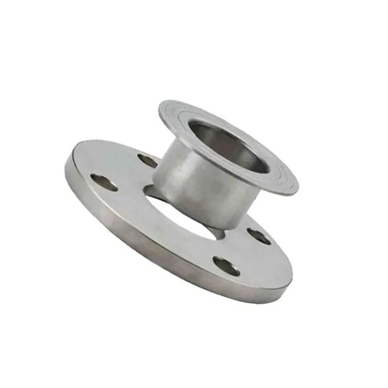 Free ring flanges Class 400
 -
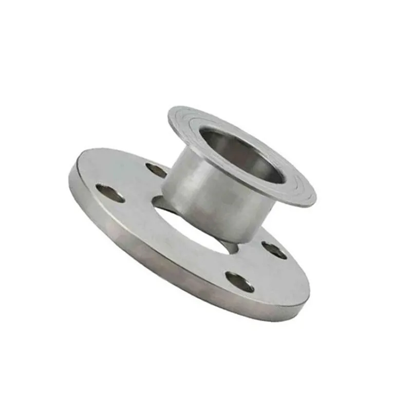 JIS 10K Loose Ring Flanges
 -
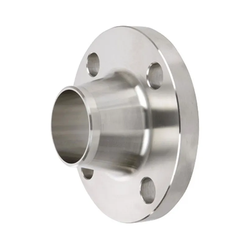 EN 1092-1 Butt weld flanges Type 11, PN25
 -
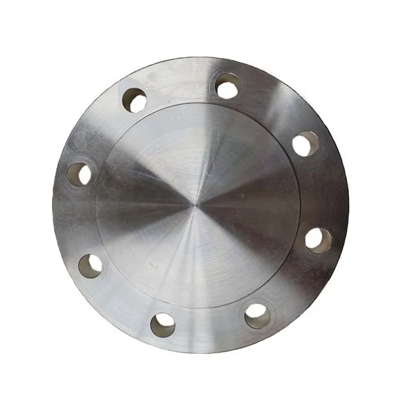 DIN 2527 Blind flanges PN10
 -
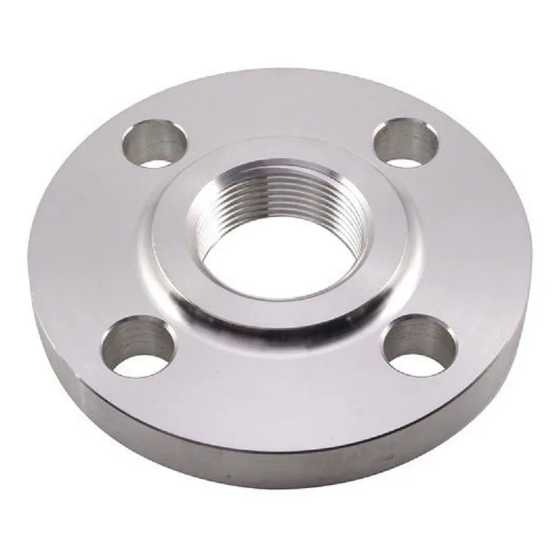 ANSI B16.5 Threaded Flanges Class 600
 -
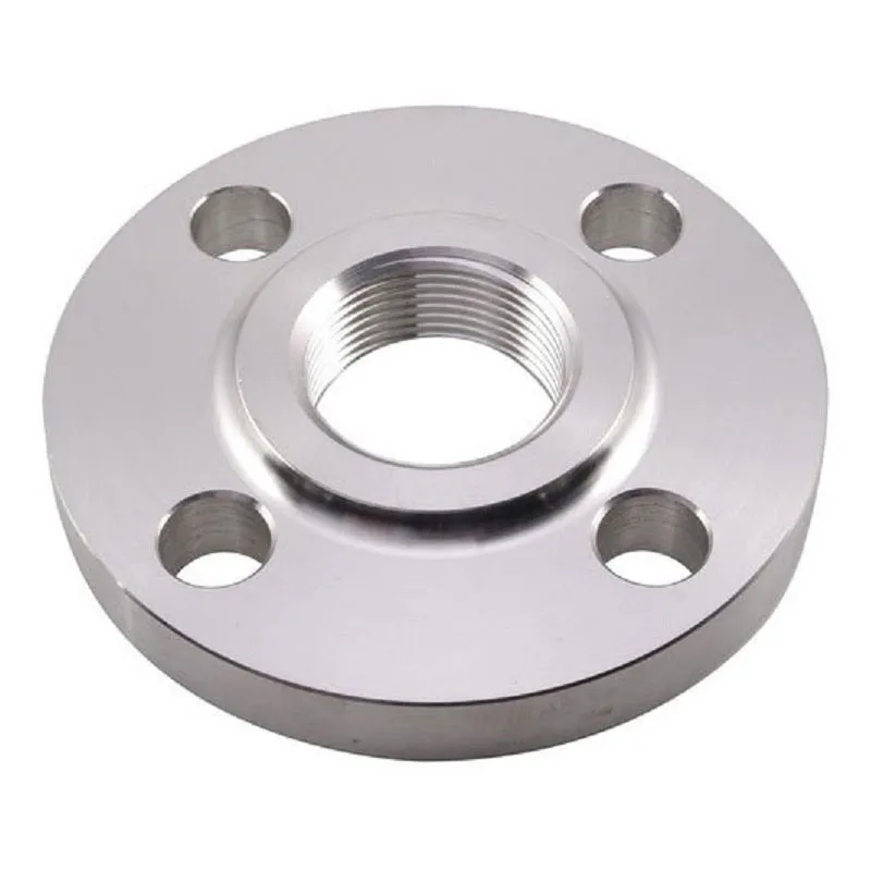 JIS 10K Threaded Flanges
 -
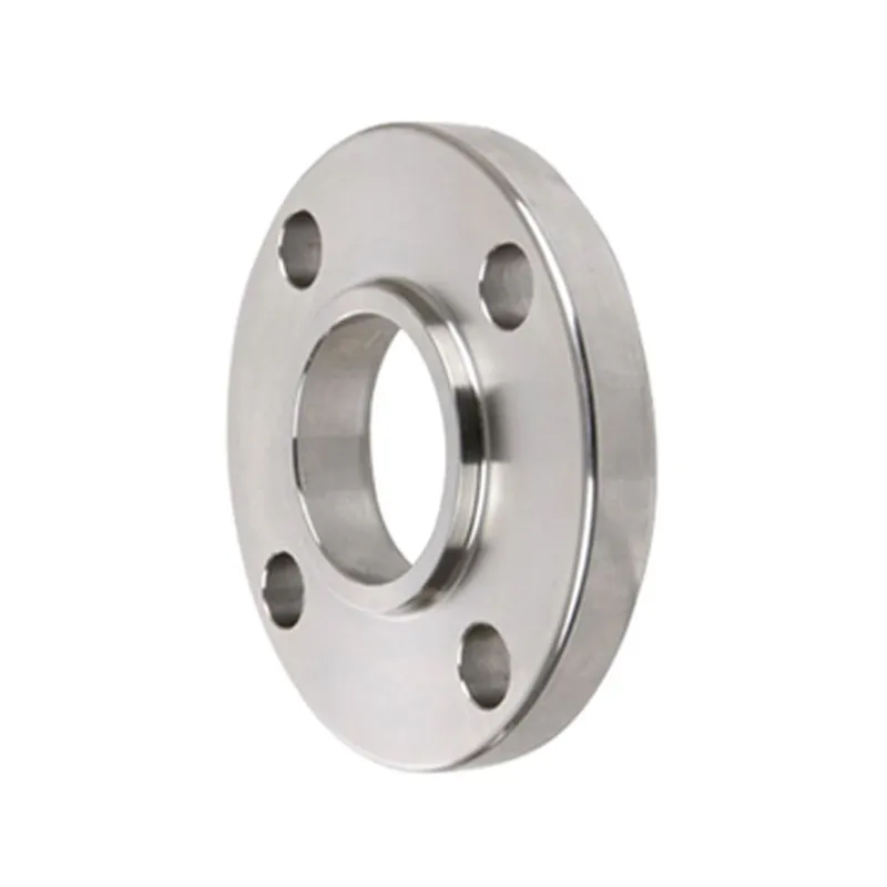 ANSI B16.5 Lap-on flanges Class 300
 -
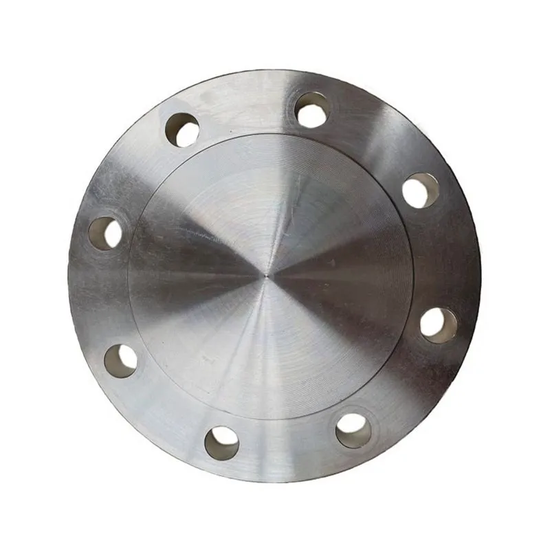 ASME B16.47 Ser.A Blind Flanges Class 400
 -
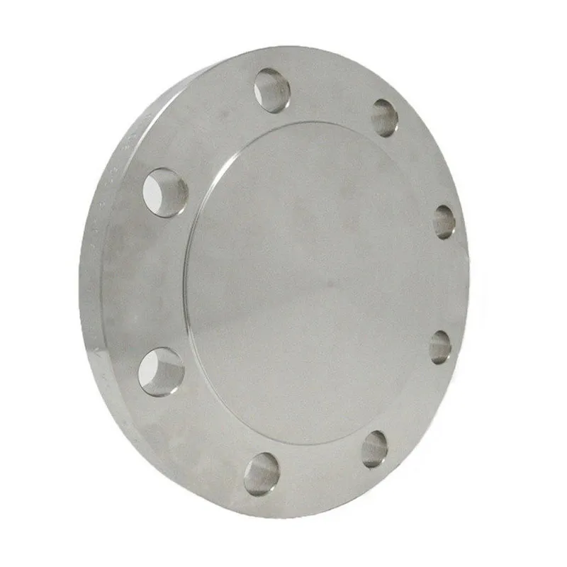 Blind flanges Class 150
 -
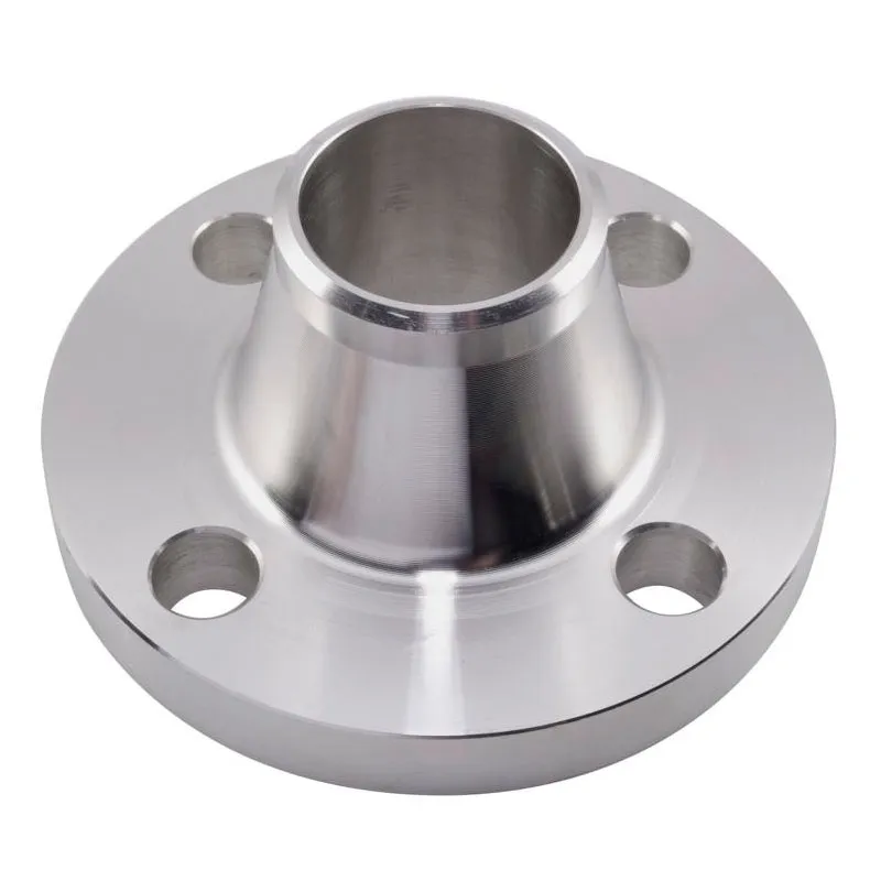 Butt weld flanges Class 900
 -
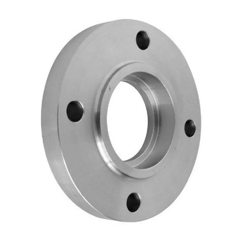 Socket Weld Flanges Class 300
 -
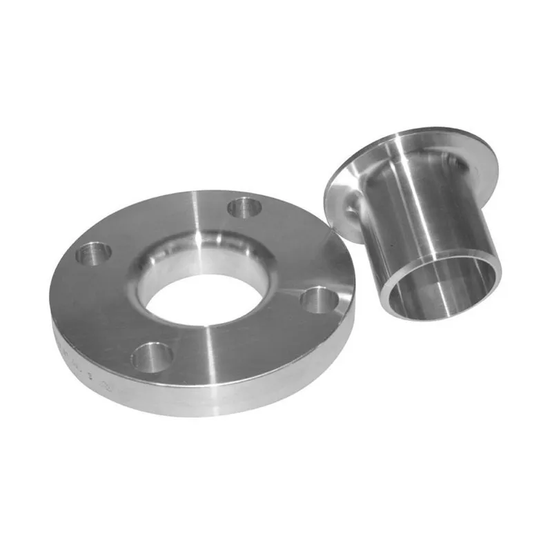 Free ring flanges Class 150